L. Váradi
Fish Culture Research Institute
Szarvas, Hungary
1. INTRODUCTION
2. HERDING OPERATIONS
3. CATCHING OPERATIONS
4. FISH SORTING
5. REFERENCES
Harvesting is a complex operation that can be divided into three major parts, as follows:
- driving and concentrating the fish stock to the catch basin;
- lifting the fish out of the catch basin and placing them on a sorting table;
- sorting the fish and loading them on the transporting vehicle.
2.1 Mechanical Driving
2.2 Hydraulic Driving
2.3 Electrical Driving
The driving and concentration of fish can be accomplished by three different ways, or by a combination of these, as follows:
- mechanical driving by different nets;
- hydraulic driving, i.e. draining the fish together with the water;
- electrical driving (by electric grid).
The mechanical driving of the fish by seines is the most commonly used method. When the fish pond is large, the netting should be mechanized because of the high pulling force. In some cases conventional motorboats, tractors or trucks can be applied for pulling the net, but special winches have been developed for this purpose (Figure 1).
During hydraulic driving the fish are carried from the pond into the catch basin by water current as the water is draining from the pond. The pond and the drainage canal should be drained completely. The hydraulic drive is sometimes combined with mechanical or electrical drives. Open drainage canals are proposed to be built in these systems because the fish have a tendency to remain inside the dark underground pipe, even if the conditions are not good there.
Electric grids or electrified seines can also be used for driving, where the electric field forces the fish to swim towards the catch basin. Electrified fish driving devices are shown in Figure 2.
Since some species of fish have a habit of swimming towards fresh inflow water, these fish species can be attracted to the catch basin by ensuring oxygen rich inflow water there. This can be combined with the above mentioned driving methods.
Lifting the fish out of the catch basin is a critical process because the fish are separated from their natural living medium: therefore, gentle handling is needed. Moreover, this process has to be intermeshed with the driving of fish into the catch basin and with sorting and transporting. Different lifting devices have been developed for fish harvesting, but the two major groups are mechanical and hydraulic devices.
Mechanical fish lifting can be classified as follows:
- devices with intermittent operationmechanized dip net- devices with continuous operation
bucket with alternate movementconveyor belt
screw
bucket with rotating movement.
Figure 1 Seine pulling devices a) Type ML-43 motor operated seine pulling winch (USSR)
Figure 1 Seine pulling devices b) Schematic of haul seining procedure by winch with two drums (USA)
Figure 2. Electric fish driving devices a) The electrode system of ERG-1-8/1 electric fish driving device (USSR)

Figure 2. Electric fish driving devices b) Electric diagram of MG screen (Poland)

Figure 3. Mechanized dip net (GRD)
Figure 4. Bucket elevators a) Mobile bucket elevator (USSR)
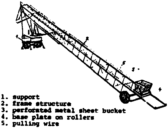
Figure 4. Bucket elevators b) Bucket elevator built in a concrete structure (Poland)

Mechanized dip nets are usually a mobile type of equipment and can be used widely, but two or three men are needed for the operation. Figure 3 shows a mechanized dip net.
The fish can be lifted out of the catch basin by a mechanized bucket elevator (Figure 4). One man can operate this device with a control panel but its installation is fairly complicated. It can only be installed in a well built concrete structure. During harvesting, the fish may have contact with hard solid surfaces and one should account for some injuries.
Ordinary agricultural conveyor belts can be used for fish lifting as well, but specially designed conveyor belts have also been developed with soft rubber belts and covers (Figure 5). These belts are mobile equipment and can be widely used, especially when the fish have to be lifted up to a fairly high elevation. The lower hopper of the belts can be filled by hand or by some device like a mechanized dip net, air lift pump, etc.
Special fish screws have been developed recently for lifting fish (Figure 6). The internal spiral ribbon and the pipe housing revolve together lifting up the water in the space between the spiral ribbon and the housing. The applicability of the fish screws is the same as that of fish conveyor belts. However, the screw makes for more careful fish handling since the fish are lifted in water.
Some other types of fish lifts with continuous operation have also been constructed where buckets are fixed to an endless chain or when a big rotating wheel with chambers is lifting the fish (Figure 7). However, these are not so widely used, mostly because of their fairly complicated installation and operation.
The working principle of hydraulic fish lifting is basically different from that of mechanical lifting, as it is the water which is lifted directly and not the fish. Hydraulic fish lifting devices are usually water pumps which have been modified according to the special needs of fish lifting.
Hydraulic fish lifting devices or fish pumps can be divided into three groups, as follows:
- centrifugal fish pumps
- air lift pumps
- vacuum pumps
Centrifugal fish pumps were first used in marine fishing vessels and, later on, in pond fish farming. These centrifugal pumps caused serious damage on 2-5 percent of the harvested fish by their impellers (Figure 8a). Special impellers were later developed (Figure 8b) and the damage to the fish decreased. Recently, well designed centrifugal fish pumps became available and are commonly used, mostly in trout farms (Figure 9). However the size of the fish is limited when using a centrifugal fish pump.
Air lift pumps are used in water management for delivery of water containing solid particles. The principle was adapted successfully for fish lifting, and special air lift pumps have been designed. Even big fish can be lifted without any damage, as there is no moving part inside the delivery pipe, only air bubbles. Figure 10 shows a plan of a mechanized harvesting place with air lift pump. In Figure 11 the water delivery pipe is shown.
Vacuum pumps are shown in Figure 12. The operation of these pumps is intermittent and they can, therefore, be used most efficiently in small units (cages) where the whole stock can be sucked into the container during one cycle. These pumps can also be used for mud removal.
The harvested fish stock can be sorted according to size and, in polyculture, according to species. When the fish stock is sorted into species it has to be done by hand and the mechanization is restricted to transporting the fish to the feeding table. Usually a horizontal conveyor belt is built into the table that conveys the dominant fish of the polyculture, and only the other species have to be touched by hand and placed aside.
The fish can be sorted into size by different screens. The screen can have several pairs of ribs with an increasing distance from top to bottom (Figure 13). The distance between two ribs is adjustable according to the grading requirement. There are graders where, instead of having fixed ribs, revolving rollers are used, as shown in Figure 14.
In order to achieve more accurate grading, there are graders where the fish does not merely slide down on the slope of the table by gravity but is led by an electric motor-driven endless rubber belt with soft rubber fingers above the slot.
Different types of scales are available to weigh the fish, but the four major types are described below:
- steelyard
- spring balance
- tipping balance
- displacement type of balance.
Figures 15 shows these types of scales.
A mobile fish conveyor belt or fish screw is the most efficient method of loading the fish from the sorting table to the transporting vehicle.
The mechanization of fish harvesting does not necessarily mean total mechanization. In some cases, only one phase of the operation is mechanized but there are farms where complex mechanized harvesting lines have been installed.
Diagrams of three of these complex mechanized harvesting systems are shown in Figure 16.
Fonarev, A.L., 1977, Studies on hydraulic transportation of fish. Moskva, Pischevaja Promyshlennost
Greenland, D.C., 1974, Recent development in harvesting, grading, loading and handling pond raised catfish. Trans. Am. Soc. Agric. Eng., 17(1)
Kuli, B. and I. Csávás, 1976, A tógazdasági haltermelés gépesitése (Mechanization of pond fish production). Budapest, AGROINFORM
Kuli, B., 1976, Különbözö gépesitett lehalászási rendszerek összehasonlitó vizsgálata (Comparative trial of different mechanized harvesting methods). Gödöllö, MÉM Müszaki Intézet
Tjuktjaeva, J.S. and V. Ja Lysenko, 1974, Handbook on mechanization of processes of pond fish culture. Moskva, Pischevaja Promyshlennost
Torban, S.S., 1977, Mechanization of processes of industrial fisheries. Moskva, Pischevaja Promyshlennost
Vibert, R. (ed.). 1967, Fishing with electricity: its application to biology and management. London, Fishing News (Books) Ltd., 276 p.
Figure 5. Belt conveyor for fish lifting
Figure 6. Type CM screws for fish lifting (France)
Figure 7. Continuous operation mechanized fish lifts a) Fish lifting device with rotating bucket (Poland)

Figure 7. Continuous operation mechanized fish lifts b) Fish lifting device with chambered wheel (USSR)

Figure 8. Special impellers for centrifugal fish pump a) Impeller of Type RB centrifugal fish pump (USSR)
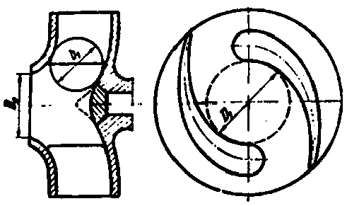
Figure 8. Special impellers for centrifugal fish pump b) Impeller of Hitachi type centrifugal fish pump (Japan)

Figure 9. Neilsen type hydraulic fish pump with dewatering tower and grader Model 5-1516 (USA)
Figure 10. The installation of the air lift pump in a mechanized harvesting place
Figure 11. Water delivery pipe of the air lift pump
Figure 12. Vacuum pump for fish harvest (GDR) a) Scheme of the operation

Figure 12. Vacuum pump for fish harvest (GDR) b) Mobil vacuum fiah pump
Figure 13. EWOS fish grader No. 2038 (Sweden)
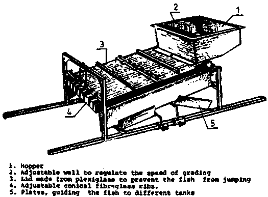
Figure 14. Fish grader Type RSG 4 with rollers (GDR)
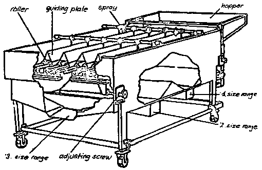
Figure 15. Scales for weighing fish a) steelyard

Figure 15. Scales for weighing fish b) SALTER spring balance (UK)

Figure 15. Scales for weighing fish c) METRIPOND No. 271. Tipping balance (Hungary)
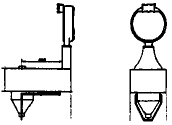
Figure 15. Scales for weighing fish d) water displacement type fish weigher (GDR)
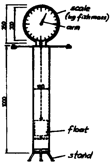
Figure 16. The scheme of complex fish harvesting systems in Hungary a) Mobile mechanized fish harvesting system (Bikal State Farm)

Figure 16. The scheme of complex fish harvesting systems in Hungary b) Stationary mechanized fish harvesting system (Hortobágy State Farm)

Figure 16. The scheme of complex fish harvesting systems in Hungary c) Central fish harvesting place with indoor sorting (Biharugra State Farm)
