5.1 When to Use Sprinkler Irrigation
5.2 Sprinkler System Layout
5.3 Operating Sprinkler Systems
5.1.1 Suitable crops
5.1.2 Suitable slopes
5.1.3 Suitable soils
5.1.4 Suitable irrigation water
Sprinkler irrigation is a method of applying irrigation water which is similar to natural rainfall. Water is distributed through a system of pipes usually by pumping. It is then sprayed into the air through sprinklers so that it breaks up into small water drops which fall to the ground. The pump supply system, sprinklers and operating conditions must be designed to enable a uniform application of water.
Sprinkler irrigation is suited for most row, field and tree crops and water can be sprayed over or under the crop canopy. However, large sprinklers are not recommended for irrigation of delicate crops such as lettuce because the large water drops produced by the sprinklers may damage the crop.
Sprinkler irrigation is adaptable to any farmable slope, whether uniform or undulating. The lateral pipes supplying water to the sprinklers should always be laid out along the land contour whenever possible. This will minimize the pressure changes at the sprinklers and provide a uniform irrigation.
Sprinklers are best suited to sandy soils with high infiltration rates although they are adaptable to most soils. The average application rate from the sprinklers (in mm/hour) is always chosen to be less than the basic infiltration rate of the soil (see Annex 2) so that surface ponding and runoff can be avoided.
Sprinklers are not suitable for soils which easily form a crust. If sprinkler irrigation is the only method available, then light fine sprays should be used. The larger sprinklers producing larger water droplets are to be avoided.
A good clean supply of water, free of suspended sediments, is required to avoid problems of sprinkler nozzle blockage and spoiling the crop by coating it with sediment.
A typical sprinkler irrigation system consists of the following components:
Pump unit
Mainline and sometimes submainlines
Laterals
Sprinklers
Figure 53 shows the mainline In the foreground, to which the laterals, with the sprinklers, are connected.
The pump unit is usually a centrifugal pump which takes water from the source and provides adequate pressure for delivery into the pipe system.
Figure 53 An example of a sprinkler irrigation system layout
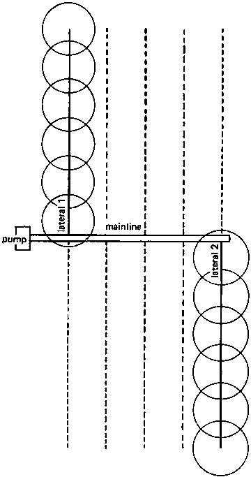
Figure 54 Hand-moved sprinkler system using two laterals (Laterals 1 and 2 in position 1)

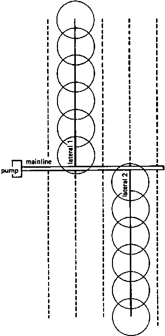
Figure 54 Hand-moved sprinkler system using two laterals (Laterals 1 and 2 in position 2)

The mainline - and submainlines - are pipes which deliver water from the pump to the laterals. In some cases these pipelines are permanent and are laid on the soil surface or buried below ground. In other cases they are temporary, and can be moved from field to field. The main pipe materials used include asbestos cement, plastic or aluminium alloy.
The laterals deliver water from the mainlines or submainlines to the sprinklers. They can be permanent but more often they are portable and made of aluminium alloy or plastic so that they can be moved easily.
The most common type of sprinkler system layout is shown in Figure 54. It consists of a system of lightweight aluminium or plastic pipes which are moved by hand. The rotary sprinklers are usually spaced 9-24 m apart along the lateral which is normally 5-12.5 cm in diameter. This is so it can be carried easily. The lateral pipe is located in the field until the irrigation is complete. The pump is then switched off and the lateral is disconnected from the mainline and moved to the next location (Figure 55). It is re-assembled and connected to the mainline and the irrigation begins again. The lateral can be moved one to four times a day. It is gradually moved around the field until the whole field is irrigated. This is the simplest of all systems. Some use more than one lateral to irrigate larger areas (see Figure 54).
A common problem with sprinkler irrigation is the large labour force needed to move the pipes and sprinklers around the field (Figure 55). In some places such labour may not be available and may also be costly. To overcome this problem many mobile systems have been developed such as the hose reel raingun and the centre pivot.
However, these systems go beyond the scope of this introduction to sprinkler systems. An example of such a complex system is shown in Figure 56.
Figure 56 An example of a sophisticated sprinkler irrigation system
Another system which does not need a large labour force is the drag-hose sprinkler system. Main and laterals are buried PVC pipes: one lateral covers three positions. For example, in the sprinkler system of Figure 53, only four buried laterals would be needed, in positions 2, and 5. Sprinklers on risers carried by skids are attached to the laterals through hoses (similar to garden sprinklers). Only the skid with the sprinkler has to be moved from one position to another, which is an easy task.
5.3.1 Wetting patterns
5.3.2 Application rate
5.3.3 Sprinkler drop sizes
The main objective of a sprinkler system is to apply water as uniformly as possible to fill the root zone of the crop with water.
The wetting pattern from a single rotary sprinkler is not very uniform (Figure 57). Normally the area wetted is circular (see topview). The heaviest wetting is close to the sprinkler (see sideview). For good uniformity several sprinklers must be operated close together so that their patterns overlap (Figure 58). For good uniformity the overlap should be at least 65% of the wetted diameter. This determines the maximum spacing between sprinklers.
Figure 57 Wetting pattern for a single sprinkler (TOP VIEW)

Figure 57 Wetting pattern for a single sprinkler (SIDE VIEW)

Figure 58 Wetting patterns for several sprinklers (TOP VIEW)
Figure 58 Wetting patterns for several sprinklers (SIDE VIEW)
The uniformity of sprinkler applications can be affected by wind and water pressure.
Spray from sprinklers is easily blown about by even a gentle breeze and this can seriously reduce uniformity. To reduce the effects of wind the sprinklers can be positioned more closely together.
Sprinklers will only work well at the right operating pressure recommended by the manufacturer. If the pressure is above or below this then the distribution will be affected. The most common problem is when the pressure is too low. This happens when pumps and pipes wear. Friction increases and so pressure at the sprinkler reduces. The result is that the water jet does not break up and all the water tends to fall in one area towards the outside of the wetted circle. If the pressure is too high then the distribution will also be poor. A fine spray develops which falls close to the sprinkler.
This is the average rate at which water is sprayed onto the crops and is measured in mm/hour. The application rate depends on the size of sprinkler nozzles, the operating pressure and the distance between sprinklers. When selecting a sprinkler system it is important to make sure that the average application rate is less than the basic infiltration rate of the soil (see Annex 2). In this way all the water applied will be readily absorbed by the soil and there should be no runoff.
As water sprays from a sprinkler it breaks up into small drops between 0.5 and 4.0 mm in size. The small drops fall close to the sprinkler whereas the larger ones fall close to the edge of the wetted circle. Large drops can damage delicate crops and soils and so in such conditions it is best to use the smaller sprinklers.
Drop size is also controlled by pressure and nozzle size. When the pressure is low, drops tend to be much larger as the water jet does not break up easily. So to avoid crop and soil damage use small diameter nozzles operating at or above the normal recommended operating pressure.
Figure 59 Sprinkler irrigation